This file contains many applets and takes some time to load, please, be patient.

www.neubert.net - Dr. Neubert's Website
The Entropy Reduction Laboratory

Octahedron's Tessellation:
from Medusae and Radiaria to Domes and GPS
Objective
  • Platonic Bodies are regular polyhedra with identical regular polygons as faces. The Octahedron is one of the Platonic Bodies. Platonic Spheres are the central projections of the faces onto the surface of the circumscribing unit sphere. The vertices are corners in the case of bodies and nodes in the case of spheres.
  • In the "mini anthology" Geodesic spheres, fullerenes and virus: we have concentrated on the Icosahedron and the impact of its derivatives on a great variety of phenomena. Here we shall do so for the Octahedron, which has been paid much less attention to in the past.
Rotate
a sphere
To rotate a figure drag the mouse left key pressed.
The
Octahedron
and the
Octahedral
Sphere

The Octahedron and the Octahedral Sphere
==========================================

The octahedron and octahedral octahedral sphere have:
  • 3 equivalent fourfold axes as the most predominant ones
  • 8 faces which are regular (spherical) triangles, 6 vertices
  • 12 edges of length sqr(2)/2
  • 12 arc-edges of length 2*arcsin(sqrt(2)/2)
Even though not as popular as the Icosahedron, the Octahedron is well suited to be taken as the basic geometric structure to build geodeic domes upon. Yves Poissant provides a compendium on the different Geodesic Dome Types , including the relevant definitions of dome class and dome frequency.

Exactly the same problem of finding suitable tessellations of the sphere is that of finding "optimal" geographic grids, as discussed by Kevin Sahr and Denis White in their review article on Geographic Grids, (in pdf format). Especially , what is called frequency by the dome builders is related to aperture of the geographic network designers.
As a third problem connected intimately with the geodesic dome geometry lies in the optimal placement of N electronsm on the surface of the sphere. Minimizing the electrostatic exchange energy results for adequate N generally in the geometry of Platonic spheres and their higher frequency descendants.
The
2 frequency
planar
equilateral
triangle

There is no ideal map!
=======================

An ideal map would be one which consists of congruent areas of identical size and which would allow finer and finer spatial resolution by keeping all areas congruent. In addition, all boundaries should be geodesic lines. -
Here we see (to the left) a 2 frequency planar equilateral triangle. All the sides of the 4 triangles resulting from the tessellation are of equal length and the sides of the inner triangle are each parallel to one side of the outer triangle. In the projection of this planar triangle onto the surface of the enclosing sphere, (as shown to the right) the sides (arc-edges) of the inner triangle cannot be parallel anymore to the sides (arc-edges) of the outer triangle:
The lines connecting the vertices of the outer triangle are geodesics and so are by construction the inner lines. By definition, a geodesic is part of a great circle. A great circle in turn is the intersection of a plane passing through the center of the sphere with the surface of the sphere. Therefore, by construction of this situation, no two geodesics can be parallel. As an immediate consequence it follows that the sides of the four triangles, which are equal in length if planar, cannot be all equal anymore after projection on the sphere's surface.
We conclude : There is no ideal map! Especially, ideal maps cannot be produced by higher and higher triangulation. This negative statement makes research in Global Geographic Grids equally frustrating and exiting.
The
2 frequency
equilateral
triangle
precalculated
new vertices
Here the coordinates of the projected vertices of the new triangles are calculated aforethought. The resulting figure is called a stellated figure. For the stellated figure holds: In the subsequent projection, only lines, no vertices are projected onto the surface of the sphere.
The
2 frequency
planar
equilateral
triangle
+precalculated
vertices
As to be expected by theory and here verified by experiment, the projections of both methods coincide on the sphere.
halve 2frequency
Octahedral Sphere

The 2 frequency Octahedron and Octahedral Sphere
======================================

Here we recognize - without calculation - that there are two sets of geodesic arcs: One set consists of arcs of length 2pi/6 and the other of arcs of length 2pi/8 ( Note: In the figure, which is a demi sphere, just 3 and 4 arcs of the full great circle are shown).

As an alternative to geodesic domes based on the icosahedron, geodesic domes based on the octahedron, "OCTA-Domes", have found recognition. By their fourfold symmetry, they appear not as extravagant as the icosahedron based domes of fivefold symmetry. Thus, they look more similar to conventional housing, but still offer the high efficiency use of space. It is true, that the icosahedron - having 20 faces - is naturally more "round" than the octahedron - having only 8 faces - . This is easily compensated by choosing a higher frequency in the tessellation of the octahedron.

full 2frequency
Octahedral Sphere
There are
48 lines - 32 areas = 18 vertices - 2
and thus Euler's theorem is met.

It is interesting to note - and not indeed surprising - that the optimal placement of 18 electrons on the surface of the sphere by minimizing the electrostatic exchange energy results in the geometry of this frequency 4 tesselated Platonic sphere. The total electrostatic exchange energy is unique signature for the N electron distribution. (in this case the value is 120.0845)

4 frequency octahedron
triangular base

The 4 frequency Octahedron and Octahedral Sphere
one octant
======================================

In this frequency 4 planar triangle, representing one of the eight equilateral sides of the Octahedron, there are 16 "small" equilateral triangles, 15 vertices and 30 edges ( of equal length).
4 frequency octahedron
precalculated vertices
elevated presentation
While all 30 triangular sides of the 4 frequency octahedral side are equal, there are 6 different chord lengthes in the stellated figure. These are distributed as:
  • 0.320365 6x
  • 0.438887 6x
  • 0.447213 3x
  • 0.459505 6x
  • 0.517638 6x
  • 0.577350 3x
The calculation of parameters of tesselated structures with frequency 4 and any other frequency has been programmed by Rick Bono This very covenient and reliable DOME program may be downloaded free ( runs under DOS ).
4 frequency octahedron
precalculated vertices
+ plane triangular base
elevated presentation
Again, theoretical prediction is verified by experiment, both the systems, the plane and the stellated, coincide after projection onto the sphere. Note, that the stellated triangle is anchored only at three points to the plane base triangle, - as to be expected by construction.


Longitude


Latitude


Longitude


Latitude


Longitude


Latitude


Longitude


Latitude

The latitude/longitude Coordinate System
======================================

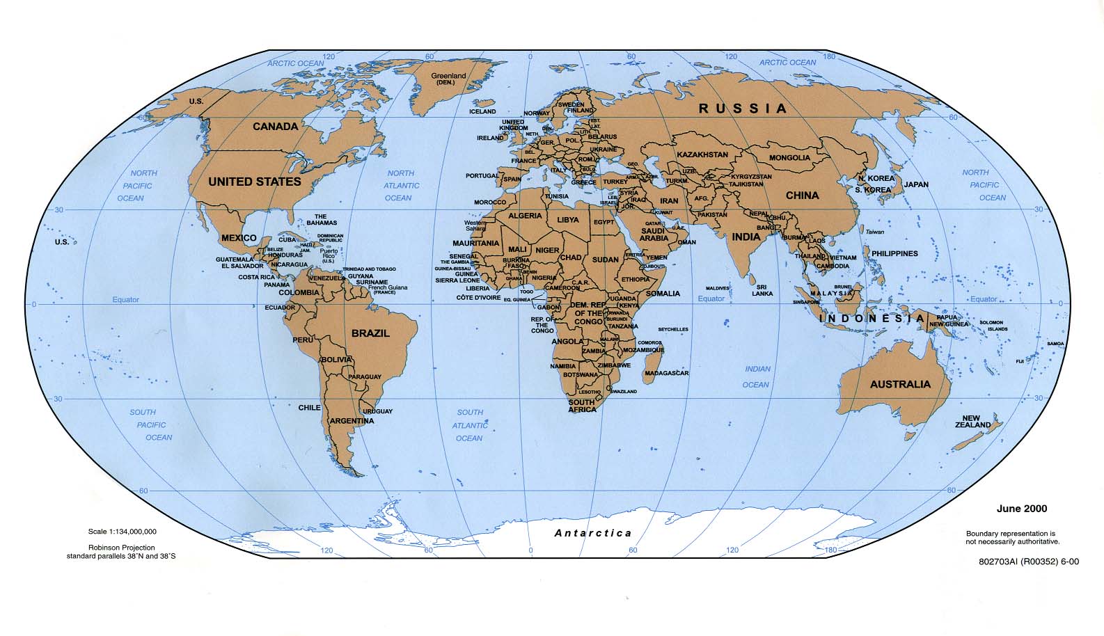
Latitude/Longitude Coordination looks at a long history. Eratosthenes calculated the Earth's circumference and he was the first to produce a map of the world based on a system of lines of latitude and longitude. Hipparchos of Nicaea (160-125 a.C), the prominent scientific astronomer and originator of spherical trigonometry, was the first to specify the positions of places on Earth by use of latitude and longitude as coordinates.

The subsequent historical development has been treated elegantly in Longitude at Sea by Albert van Helden: The age of exploration quickly exhibited the problem of navigation and mapping the newly discovered land. The dispute of Spain and Portugal over the "new world" lead Pope Alexander VI in 1493 to issue the "Bull of Demarcation". He drew a meridian one hundred leagues from the Azores and assigned to Spain all discovered land west and to Portugal all that east of the line.
Until the end of the fifteenth century, sailors navigated with almost daily reference to land. In the Mediterranean ist was difficult to get lost, at the Atlantic ships hugged the shore from Gibraltar to Norway. With the Portuguese voyages of discovery, navigation became more difficult. For some time they stayed close to the cost of Africa, exploring the coast of this continent.
With Columbus in 1492 and Vasco da Gama in 1498, Spanish and Portuguese sailors sailed the high seas for weeks without seeing land. The only reference points were the stars and the sun and it were the Portuguese who pioneered the method of navigating by latitude. With suitable instruments on board a ship it was possible to determine the latitude within one degree from the measurement of the altitude of stars and sun. Longitude was, however, a more demanding matter: In order to determine the longitude with respect to, e.g.Lisbon, one had to find out the difference in local times between one's location and Lisbon. No easy method that was sufficiently acurate suggested itself.

The dramatic development in the art and science of longitude determination arose in England in the middle of the 17th century. Groups of scientists began meeting in London and Oxford from 1645 and certainly the longitude problem was one of the main problems which they discussed, English attack on the Longitude Problem by J.J.O'Connor and E.F.Robertson..

Today, the longitude/latitude coordinate system is the most widely used.

  • Its main advantage is the fact, that for small areas A the deviations of the longitude/latitude coordinate system from orthogonality are by Girard's Theorem of the order A/R^2 (R = earth radius) and thus sufficiently small to appear "orthogonal".
  • Its main disadvantage is the extreme variation of the size of a "unit" cell in going from the equator to one of the poles. - For large scale coordination on earth alternative systems are to be taken into consideration.
Octahexon
elevated vertices
one octant

The Octahexon Figure and Sphere
==================================

This is one octant of Alan Ditchield's Octahexon. The Full Octahexon ( Word 6 doc ) has:
  • 192 vertices
  • 276 great circles arcs of equal length 13.24878114 degrees as edges
  • 80 spherical hexagons of three types
  • 6 spherical polygons, with 12 equal sides, shaped like a Greek cross
We verify that the Octahexon Figure meets Euler's condition:
276 edges -192 vertices = 86 faces - 2
ok

Some details of the construction will be disussed below.
Octahexon
elevated vertices
+ untesselated
base triangle
Here it is seen clearly, that Ditchfield's Octahexon Figure is defined not by tessellation of the Octahedron, but by tessellation directly on the sphere, using in the computation the mathematical formalism of spherical geometry. The Octahexon Figure is "floating" with respect to the original Octahedron, but well defined within the surface of the sphere.
Octahexon
demi sphere (4 octants)


Octahexon
demi sphere (4 octants)

Golden Oracle

Radiolaria

Medusae
This is the demi Octahexon. As mentioned above, a pronounced property is the "Greek cross" at the 6 nodes, lying at the north and south pole and under 90 degrees on the "equator".
A dome, called the OracleGold has been constructed by Alan Ditchfield.
It is remarcable that the greek crosses are a typical also for Radiolaria as collected by Ernst Haeckel, the originals to be seen at Ernst-Haeckel-Haus der Friedrich Schiller University in Jena, Thueringen, Germany.( Especially nice: Plate 19 (Acanthostaurus) and Plate 20) Also, this geometry is observed in the collection Henry B. Bigelow, Medusae from the Maldedive Islands, Museum of Comparative Zoology at Harvard College, Cambridge, Mass,USA. (Especially nice: Plate 1, Plate 4, and Plate 6. Apparently, nature produces tessellations of octahedral symmetry different from the typical Buckminster Fuller structures. While for "nearly flat" organisms, e.g. the SandDollar, a cap of a tesselated icosahedral structure with a fivefold rotation axis is preferred, for the more round "hemis sphere structures" an Octahexon like structure with fourfold symmetry and corresponding higher angular deficit at the pole seems to be preferred by nature.
Octahexon
full figure
(8 octants)


Octahexon
full figure
(8 octants)

Global Geographic Grid

Global Positioning System
The full Octahexon Figure may be applied to a variety of purposes. It may work as the very symmetric geometry of roughness of a golf ball. The demi Octahexon may provide the frame of a geodesic dome structure as shown above.
A hexagonal coordinate system derived from the Icosahedron is proposed in Discrete Global Grid Research at Terra Cognita, Oregon State University. This kind of coordinate system has been considered useful e.g. in setting up the General Circulation Model of Colorado State University, Ross Heikes and David A Randall.

A high resolution hexagonal grid is used also as coordinate system in the GME model of the German Weather Service

Alan Ditchfield's Honeycomb coordinate system (Word 2000 doc) based on the Icosahedron having arcs of only two different lengthes has been referred to already in the page on Geodesic spheres, fullerenes and virus. of this site.

A Discrete Global Grid based on the Octahedron reflects more the inherent longitude/latitude symmetry of the earth. Such a system is the OCTAHEXON GLOBAL GRID, as proposed by Alan Ditchfield. By its Octahexon structure it has very appealing properties:

  • It maps very naturally the natural symmetry of the rotating earth, having a north and south pole of a more important than just a geometrical reason.
  • Also the fourfold rotational axis of the octahexon maps naturally the four quadrants north and south of the globe with the zero meridian at Greenwich.
  • In addition, it consists of arcs of one length only. In other words, the distance between any two vertices is always the same - a most remarcable and useful property.
This system cannot be broken down to a finer structure. Ditchfield suggests to use the "spiral" coordination concept ( Rakhmanov, E.A., E.B.Saff, and Y.M. Zhou, Minimal discrete energy on the sphere, Mathematical Research Letters, 1, 647, 1994 and Saff, E.B. and A.B.J.Kuijlaars, Distributing many points on a sphere, Mathematical Intelligencer, 19, 5, 1997.) as proposed by Robert Raskin (Jet Propulsion Lab, Pasadena) "Practical Properties of the Spiral Points" International Conference on Discrete Global Grids, Santa Barbara, 26-28 March 2000" for large scale fine resolution. Here any vertex would be the origin of a separate spiral and there would be 192 spirals instead of just two as proposed by Raskin. Close up coordination would still rely on a a suitable local longitude/latitude grid, however, with the origins of local "nearly orthogonal" grids specified relative to the vertices.

Besides the globe, which is defined by the surface of the earth, recently a second "globe" has become of importance, the globe on which the satellites of the Global Positioning System (GPS) cruise. Since satellites' path is determined by the balance between centrifugal force and gravitational attraction to the center of the earth, satellites necessarily travel on a geodesic. (Airplanes and ships tend to do so for travel time and travel energy minimizing reasons, but they don't have to!) A hexagonal grid with Ditchfield type geodesic arcs of equal length might be a good foundation for a future "dense" satellite system. For various reasons it might be desirable, to have each of the satellites to be "active" only as long as it travels on one of the hexagon arcs and have some "duty off" time in between. Such a satellite system would move in a concerted action as a celestial quadrille, where correct timing is of outmost importance. The "globe" of the satellite courses with a radius of the order of 100 000 km would project directly onto the Global Grid System with the radius of the earth of about 7000 km.

Rotate
a sphere
Click on the selected tessellation figure and drag the mouse.
See also
other pages
of
this site.
Back To go back to the Welcome page click here.

This page and each part of it Copyright © 1998-2002 Karl-Dietrich Neubert.
All Rights Reserved
Design by Vladimir Marek.
Last update of the page: April 20, 2003